Understanding the ins and outs of electrical circuits (published June 2012)
If anything on your boat is run by electricity, sooner or later it will fail. The corrosive combo of salt and moisture provides such a hostile mixture that it is remarkable any electronics work at all. Keeping the boat clean and dry will prolong their life, but sooner or later the inevitable will happen.
Electricity has had bad press (some people are afraid of it and many proudly state a total lack of understanding), but just a little knowledge will solve most of the problems you encounter. This knowledge can not only enhance our safety, but also build confidence and independence. What may be merely an inconvenience close to home can become a major problem in an isolated anchorage. A working knowledge of electricity is well within everyone’s ability.
WHAT ARE VOLTS, AMPS AND WATTS?
Allow me to let you in on a little secret: electricity is nothing more than a flow of energy that starts at one side of an energy source and flows through a circuit consisting of wire and an appliance—a light globe or radio, for example—then back to the other side of the energy source. The energy source can be a battery or alternator supplying direct current (DC) or an onboard generator or even a shore connection supplying alternating current (AC).
There are three parts of this circuit—the supply voltage or electrical pressure that causes it all to happen; the flow of energy or current (the volume of electrical energy); and the resistance (or opposition to the current) of the circuit (the wire and the appliance). While this relationship is defined more precisely by Ohm’s law, all you need to remember is that the amount of current is determined by the supply voltage and the resistance of the circuit. In practical terms, a high resistance circuit—like LED light—has a small amount of current, while a low resistance circuit—say an anchor windlass—has a much higher flow of electricity.
When manufacturers state the electrical consumption of their appliances, some note the operating current while others use the power consumption. Fortunately, there is a simple mathematical relationship. Power (watts) is calculated by multiplying the current (amperes) by the voltage. So, if you know any two, then you can work out the third.
HOW TO MEASURE ELECTRICAL PARAMETERS
A volt meter measures the voltage or electrical pressure that pushes the current around a circuit. To measure the voltage, we place the volt meter across (or in parallel to) the supply. Because of this, volt meters have a very high internal resistance, so they do not load or take away anything from the circuit being measured.
An ammeter measures the current in amps, or volume, of electricity passing through the circuit, so it is placed in line (or in series) with the circuit. To prevent it from affecting the reading, it needs to have a very low resistance to the electricity flowing through it. You must never place a meter set to amps across any circuit, as it will simply short circuit the part you are trying to test, damage the circuit, possibly kill the meter and make any reading meaningless.
Ammeters and volt meters can be panel mounted or they can be portable.
DIGITAL AND ANALOG
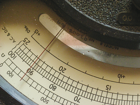
Digital meters display the voltage reading in plain numbers, while analog displays show the result with a needle moving across a scale. Each has its benefits and limitations. An analog meter does not need an internal battery to read the basic voltage and current, while a digital meter needs an internal battery to power it. Analog meters are better if the value is changing, but digital meters will display a steady voltage with more precision—useful if determining the state of a battery where the difference between a charged and discharged battery is little more than one volt.
USING THE METER

Rule 1: Don’t blow yourself up. Most batteries and engine-driven DC charging circuits found on a boat operate at a relatively low voltage (usually 12V or 24V, very occasionally 48V). Leave the 110 volts AC to a qualified technician; it can cause serious injury or be fatal whether from shore power, local generator or shipboard inverter. While a 12 or 24 volt battery is not a lethal voltage, it can deliver an astonishingly high current that can melt metal objects, including a carelessly placed ammeter, wedding ring, metal tool, etc.
Rule 2: Don’t blow up the meter. Before you start poking around with an analog meter, make sure the positive and negative probes are connected to the positive and negative side of the circuit. If you are measuring volts, set the meter to the next highest range above the battery voltage (12 or 24 volts) you are testing. If measuring current, think about the likely value, and if it is within the meter’s capability, set the meter to the highest range (10A on most available meters), then reduce it until you have a sensible reading. A digital meter will show a display even if the probes are connected wrong way around (positive probe to the negative side of the circuit). It will display a minus sign before the reading in this case.
Rule 3: Don’t blow up the circuit. Most boat circuits are robust enough to survive someone going for a look around with a properly set up meter. Follow this advice and you should be safe for most wiring faults. But, be wary of opening up electronic devices. Transistor circuits are particularly vulnerable to stray static voltages. These charges, surprisingly many thousands of volts, can be conducted into the circuit simply by poking meter probes or fingers around and destroying delicate components. Modern radio receivers, autopilots and computers are especially vulnerable. And if you mistakenly poke a meter set to amps when you really meant to set it to volts, expect to melt something expensive; most of these devices are not repairable, so you will be up for a new one.

CAN YOU BELIEVE WHAT YOU SEE?
The accuracy of an analog meter is defined as a percentage of the scale you select (typically ± 1%). So if you select the 100V scale to measure 12V, the error will be ± 1% of 100V, giving a result somewhere between 11 and 13 Volts. Using the 20V range reduces the error to only ± 0.2V, reducing the uncertainty to between 11.8 and 12.2V.
Digital meters are not susceptible to these errors. While some modern digital meters auto range (display the voltage irrespective of the scale setting), the scale setting will usually determine how many digits are displayed on the screen. Set it for at least two decimal places. Also, a digital meter will usually show an error message or symbol if it cannot display a valid reading. Reading accuracy will be listed in the meter specifications, but is often 0.5% or better.
RESISTANCE MEASUREMENT
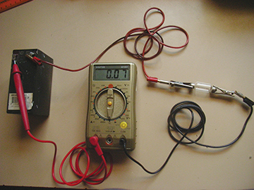
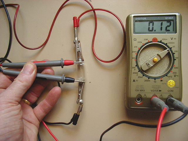
Resistance is the electrical opposition to the flow of current through a circuit. A simple and practical use for this type of measurement is to check if a circuit is continuous (test a fuse or a light globe). By setting the meter to resistance, the needle or digital display will show the measured resistance of the circuit or device. It is a good test to check if a masthead lamp is intact without having to do the climb. If you get a resistance reading (around 5 ohms) at the base of the mast, then the globe and wiring are probably intact. The unit of resistance is the ohm, its symbol the Greek letter Ω. Before taking a resistance reading, touch the probes together and use the ohms adjustment (usually only on analog meters) to set the pointer to zero. This compensates for any resistance in the probes for the measurement you are about to make.
CARE OF THE METER
Do not expose any meter to extreme heat or cold. Keep it dry, especially from sea water, and do not drop it. The delicate coil in an analog meter is similar to a hairspring in an old watch and is particularly susceptible to shock; digital displays can shatter.
Always switch off when not in use. If there is no off switch on an analog meter, set the switch to the highest AC voltage range available. Check any internal batteries regularly, as they may leak (analog meters have these for resistance readings); this is usually the end of the meter.
SO, HOW DOES IT ALL WORK?
There are two common problems that occur with an electric circuit; open or short circuits. An open circuit occurs when part of the circuit has broken. On a boat, this is generally due to corrosion in a connector or a wire fractured due to vibration.
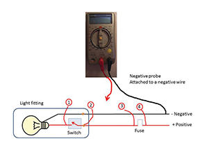
Let’s take a simple case study: a cabin light has stopped working. There is no one right way to finding open circuit faults, but here is my method. First, test the globe and fuse with your meter set to resistance as discussed earlier. While you have these out, check for any signs of corrosion on the metal contact area—a white or green powdery residue or very dull metal. Clean the contact areas with fine emery paper or any other lightly abrasive pad. While you are at it, check the contacts in the light fitting as they could also be dirty. If both test clear, check to see whether the electricity is getting to the light fitting. One side of the switch will go back to the fuse panel and the other will go the globe; note that switches should be wired in the red or positive wire; the circuit for this is shown on page 47. Check the wires and connectors—they should be clean with no green or black corrosion and intact. Pull each one gently to see if they are sound. Often, connectors can be loose, which is a common point of failure.
Turn the switch on, replace the fuse, place the positive probe onto the globe contact (position 1 on the diagram) and put the negative probe onto the negative wire on the switch. If there is a reading (usually around 12.5V), go back and look more carefully at the globe and contacts. If there is no reading, try the wire leading into the switch (position 2); if the switch is faulty there will be a reading on the wire from the fuse panel and not on the contact leading to the globe. This proves that the switch is corroded or faulty internally. If no luck here, open the fuse panel and place the positive probe onto the wire on the appliance side of the fuse (position 3) and the negative probe onto a convenient negative wire. If there is a reading here, then the wire from the fuse panel to the fitting is broken somewhere and you will need to start looking into all the places the wires run.
Finally, if there is no reading on the fuse, check the bus wiring position 4; this is the wire that runs along all the fuses and leads straight back towards the battery. Of course if there is no voltage here then you would expect other appliances to not be functioning! The problem can also be due to a broken (open circuit) negative wire, but the principle is the same; logically follow the trail until you get a reading.
A variant of an open circuit fault is a high resistance in the circuit. This reduces the current available to the appliance, preventing it from getting enough energy to operate properly. With a motor (refrigerator, bilge pump for example), not getting enough current can cause it to burn out—a light globe will glow dull red and fluorescent or LED lamps may not turn on at all. Nearly all high resistance faults can be attributed to corrosion due to moisture; something that is impossible to avoid in a boat.
Unfortunately, some suppliers are more interested in profit than quality and use totally unsuitable materials for the job. I have seen cheap automotive connectors made of inferior brass corrode within a few weeks in the marine environment. Screw connectors not properly sealed can corrode and if the screw connection is not adequately tightened, then you have another potential breakdown. Wire not UL rated for marine use will corrode rapidly. Marine grade wire should be tinned (it looks silver rather than the copper color of uncoated wire) and insulated with PVC—the only insulation really impervious to water. The best method of avoiding most of these problems is not to have joins. If you have no choice, the only sure solution is to replace the faulty connector or (my preference) solder the joint and sheath it in glue-lined heat shrink tube. Finding these faults is relatively straightforward, as most can be found by simple inspection. A good join or switch will have next to no resistance and so, while the appliance is turned on, the voltage dropped over it should similarly be zero. If there is any significant resistance present, then a volt meter placed in parallel with the join or switch will show a significant voltage reading of a couple of volts or more.
With very high current loads (anchor windlass, engine starter motor or alternator), high resistance problems become crucial. A friend of mine had problems starting his diesel. The starter did not spin the engine fast enough and he saw smoke coming from the engine compartment. There were a number of problems that—while no one by itself may have been responsible—combined to cause the trouble. First, the bolts on the battery terminal were not tight—this was the source of the smoke, and the heat generated was burning the cable insulation. The second was a bent terminal at the battery; this had the effect of reducing the surface area and increasing the resistance at the join. Finally, he had installed a bilge pump and solar panel directly on the battery, but under the starter cable. The effect of this was that all the starting current (several hundred amperes) had to pass through these small connectors; they should have been placed on the top of the larger high-current terminal directly on the battery. Perhaps a better arrangement would have been to bolt a bus bar onto the battery to take the small current loads that he wanted to connect directly to the battery.
Short circuits occur between two wires or between a positive wire and a metal part of the boat. Wiring that is in contact with a sharp protrusion—particularly on a metal boat, part of the engine or a frame—will eventually wear insulation through, causing the current to flow through the fault and not the appliance. Often, this causes the fuse to blow or the circuit breaker to trip out; if these have not been fitted then insulation can burn and even catch fire. Inspecting the wire run is a good first step as these faults tend to be visible on bends, where a nail or screw has pushed through the wiring or some other mechanical fitting has intruded. While I favor using a test lamp, it is possible to use a meter.

Remove the fuse and place the meter set to resistance across the side of the fuse base that leads to the appliance and a negative terminal. Be very careful here, as you can damage the meter if you place the probe on the live side of the fuse. If the meter is fitted with a tone that sounds when the short circuit is present, the task is greatly simplified as you simply open the wire run at strategic places until the tone stops—then you have found the fault. A variation of the short circuit fault is a high resistance across the two wires. These are more often due to moisture in a connecting box or corrosion at switch terminals. All you can do is inspect each point along the wire run and dry it. Methylated spirits will absorb moisture; just be aware that you are using a flammable fluid. Damp salt is an excellent conductor of electricity.
John Tylor is a retired electrical engineer who lives in the Blue Mountains west of Sydney, Australia. He and his wife Patsy cruise the east coast of Australia when they can, but he is currently upgrading their venerable Duncanson 35 yacht Ard Righ, which means ‘The High King’ in the Celtic language. John has repaired the electrics on many yachts and gains his inspiration from these experiences as well as from the many upgrades to his own boat.
RELATIONSHIP BETWEEN ELECTRICAL PARAMETERS (OHM’S LAW)
The mathematical relationship between the three electrical parameters is stated as
Current = Voltage ÷ Resistance. For example: current (I) = 12 volts ÷ 30 ohms. In this simple circuit, the resulting current is 0.4 ampere.
The power consumed by a circuit is given in watts. For example, a light globe of 24 watts will draw 2 amperes from a 12 volt battery.
Power (W) = Current (I) x Volts (V)
Power (W) = 2 Amps x 12 Volts


